|
| |
 |
Slurry / Pilot Testing
FFP Provides pilot Slurry Testing on site in our lab. we are able to offer various types of filter press pilot press units for rent.
|
| |
|
|
|
 |
|
 |
A BASIC INTRODUCTION TO FILTER PRESSES
FOR SLUDGE DEWATERING, FILTRATION
AND PROCESS FLUID POLISHING
|
The intention is to provide an introduction to Filter Press technology as it applies to sludge dewatering and filtration and provide the basic facts for an understanding of these processes. |
| |
|
| |
|
 |
|
|
|
Introduction
Sludge dewatering using filter presses has become accepted as a reliable and efficient method of dewatering effluents and sludges from industrial and municipal waste treatment processes. Some typical applications include:
- Metal hydroxide sludge
- Brine sludge
- Secondary biological sludge
- Water treatment alum sludge
- Oily sludge
One of the most difficult problems today is the disposal of sludges in waste treatment. Dewatered sludges from traditional dewatering equipment, (i.e. rotary vacuum drum filters, centrifuges and belt presses), are less acceptable for disposal in landfills and due to their high moisture content they are not economical feasible. The filter press process results in drier sludge that has proven to be an effective solution to this problem.
For example – sludges (such as alum sludge and waste activated sludge) that were previously considered difficult to dewater on traditional equipment can now be dewatered in a filter press sufficiently to produce a hard, dry, easily handled and autogenous material for incineration.
|
|
|
|
|
|
|
The Filter Press
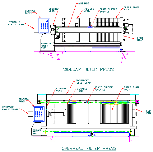
The filter press basically consists of a number of chamber filter plates (also referred to as recessed filter plate pack) mounted vertically on and between two sidebars or suspended from an overhead support beam. The support beam or sidebars are connected at one end to a fixed head, also known as a feed head, and at the other end to a closing head. Through a closing arrangement on the closing head, usually a hydraulic ram, the recessed filter plate pack is compressed tightly together between the fixed feed head an a third head know as the moving or follower head, thus forming a compact filtering unit using recessed chamber filter plates or flush plates and frames.
 |
The filter cake chambers are formed in either of two ways: by mating two recessed chamber plates or by two flush plates with a cake frame (much like a picture frame) sandwiched in between.
The two faces of the filter plate have a drainage surface in the form of ribs, grooves or pips to allow filtrate to drain behind the cloth to the drainage ports located in each corner of the filter plates. These ports, in turn, connect to the corner eyes, which carry the filtrate drainage to the fixed end of the filter press.
A filter cloth is mounted over each of the two faces of the filter plate. The cloth is joined at the feed eye by an impervious sleeve or tube also known as a barrel neck.
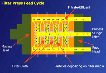
Filter Press Feed Cycle
Step 1
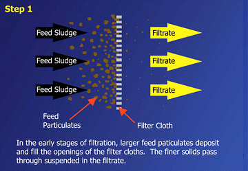
Sludge is fed into the filter press by a suitable pumping system and passes through the feed eye of the succeeding plates along the length of the plate pack until all chambers are full of slurry. This is known as the fast fill portion of the filter cycle.
Step 2
Flowing under pressure, the solid particles begin to deposit on the surface of the filter cloth forming the initial layer of filter cake referred to as the pre-coat. Once applied, this pre-coat layer becomes the actual filtering medium.
Step 3
As filtering continues the cake thickness gradually increases, until the adjacent filter cake in each chamber touch or bridge. At this point of the filter cycle, the dewatering phase enters into final cake consolidation to achieve maximum cake dryness (Refer to figures 1 to 6).
 |
|
 |
Figure 1 |
|
Figure 2 |
| |
|
|
 |
|
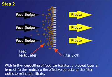 |
Figure 3 |
|
Figure 4 |
| |
|
|
 |
|
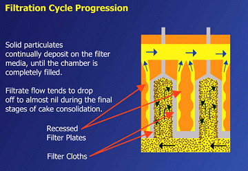 |
Figure 5 |
|
Figure 6 |
Final Cake Consolidation
During the consolidation step of the cycle, additional solids are being pumped into the filter chamber to displace more liquid. This results in a dryer, firmer and denser filter cake. This cycle normally continues until liquid flow from the press is reduced to virtually nil. At this point, the feed pump is stopped and the internal pressure within the filter plate pack is relieved.
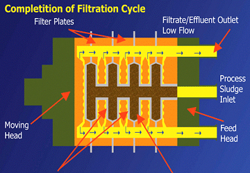 |
Figure 7 |
Prior to discharging the filter cake, the cake may be further washed in place for extraction of impurities or neutralization purposes and/or the cake may be blown with air to further remove free moisture and to dry the filter cake (See Section 9 for further explanation).
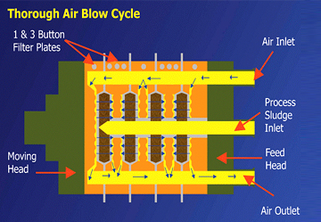 |
Figure 8 |
With pressure relieved within the filter plate pack, the hydraulic closure system is actuated to retract the moving head to its fully open position. Once open, each individual filter plate is separated from its adjacent neighbor allowing the filter cake to fall freely from between the separated chambers. Depending upon the size of the press, the plates may be moved manually or by a semi or fully mechanized plate-shifting device.
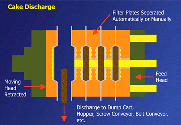 |
Figure 9 |
In most cases mechanized filter presses are preferred for sludge dewatering due to the large number of pressing cycles required in a given period of time.
With fully mechanized plate shifting devices, the transport speed is adjustable, but averages 6 to 8 plates per minute.
After the filter cake has been fully discharged the filter cycle is complete. At this point the press hydraulic system will shut off and the filter press will go into the stand-by mode until another filter cycle is ready to begin.
To begin the next filter cycle, the hydraulic closure system is activated to extend the moving head back to its closed position. As a result, the complete filter plate pack is pushed back and sealed in an operating position. At this point, the filter press is ready to begin another cycle.
|
|
|
|
|
|
|
Basic Sludge Dewatering System And Performance
The typical filter press dewatering system includes the filter press, sludge feed pumps as well as sludge storage and/or sludge conditioning tanks with slow speed mixers, sludge transfer pumps, chemical feed, storage equipment, necessary piping, valves, and controls. Two types of filter press systems are available:
a) High Pressure (i.e. 225 PSI or 16 Bar)
b) Low Pressure (i.e. 100 PSI or 7 Bar)
Many sludge-dewatering filter press systems are designed for automatic system operation from a main control panel. A typical line flow diagram is shown in Figure 10.
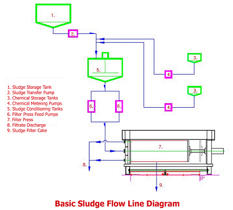 |
Figure 10 |
During the initial step of the filter press dewatering cycle, the filtrate flow from a large press can be as much as 10,000 to 20,000 gallons per hour. This part of the cycle is often referred to as the fast fill. During this period the cake chambers of the filter press collect the major amount of sludge solids. As the chambers become progressively more filled with sludge solids, the pressure inside the filter press plate pack rises and the filtrate flow rapidly decreases.
Towards the end of the cycle, the filtrate flow gradually drops to virtually nothing. This portion of the cycle is referred to as the cake consolidation step. During the cake consolidation step, more sludge solids are being forced under pressure into the cake chambers, which in turn displaces more water from the loosely formed sludge cake. This enables the filter press to produce harder and drier sludge cakes than other methods of dewatering.
Factors effecting cycle time are: the type of sludge and sludge feed concentration. Generally speaking, the higher the sludge feed concentration, the shorter the cycle time.
An average cycle time for a typical metal hydroxide sludge would be in the range of 1 to 3 hours, but can be as much as 4 to 6 hours for more difficult sludges such as an alum sludge.
In some applications, i.e. base metal concentrate slurries, where the feed concentration can be as high as 40% to 50% by weight, the cycles can be as short as 5 to 10 minutes.
Typical results from the filter press are expressed in percent cake dry solids by weight in Table 1 below.
| TYPE OF SLUDGE |
% CAKE SOLIDS |
| Biological waste activated sludge |
30% to 40% |
| Metal hydroxide sludge |
30% to 55% |
| Alum water treatment sludge |
25% to 35% |
| Oil refinery sludge |
40% to 50% |
| Lime Sludge |
30% to 60% |
| Brine Sludge |
60% to 70% |
A wide range of sludges can be effectively dewatered at pressures as low as 7bar (100 PSI). For more difficult applications like Biological water activated sludge, alum sludge, or where maximum cake dryness is required, high-pressure 16bar (225 PSI) filter presses are generally utilized.
Filter Cloths
The filter cloths are woven fabrics using monofilament or multifilament synthetic fibers or a combination of both. The most commonly used materials are polypropylene, polyester, and nylon. Filter cloths are primarily selected for filtration, strength, and cake release properties. With the proper cloth selection, good cloth life (typically 1500 to 1800 cycles) and good cake release from the filter cloth can be expected.
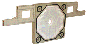
Filter cloth style is typically dependent on the type of filter plate selected for the application. Illustrated below are two types of filter plates; Caulked and gasket recess filter plate (Figure 11) where a cord is sewn into the filter cloth to secure the cloth into the cloth-retaining groove in the filter plate. Recessed filter plate (Figure 12) where the filter cloth is secured by cloth dog pins and/or electrical ties.
 |
|
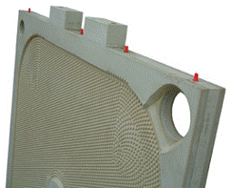 |
Figure 11 |
|
Figure 12 |
|
|
|
|
|
|
|
Sludge Conditioning
Many types of industrial sludge, such as metal hydroxide sludge, can be dewatered in a filter press without any pretreatment other than that required for pH correction.
In most instances, biological waste activated sludge (sludges) where a large percentage of organic materials are present, require chemical treatment or conditioning to render the sludge suitable for dewatering in a filter press.
Effective sludge conditioning or pretreatment is defined by any changes to the raw sludge that effectively reduce viscosity, resistance to flow, increase filtration rates or increase solids concentration in the sludge feed. These changes can be made chemically or physically.
Chemically conditioning the sludge involves coagulation and flocculation of the sludge fine particles to produce a filterable floc structure.
The physical means of conditioning sludge include processes such as heat treating and freezing.
A third method of rendering sludge more filterable is the introduction of bulking agents; filter aid (diatomaceous earth), fly ash or any other solid, which would provide porosity in the sludge cake to enhance filterability.
When considering costs such as capital equipment, conditioning agents, transportation and handling of conditioning agents. Chemical conditioning, in most cases, will prove to be the most economical and by far is the most generally used method of treatment.
Primary coagulants of the trivalent salt classification tend to produce the most stable flocs for filter pressing, although with proper pH control, high molecular weight polyelectrolytes can be used with good results.
Good floc stability and strength is of the utmost importance. A weak floc will collapse easily under filtration pressure or will shear within the filter press and impair filtration performance.
Commonly used conditioners for sludge treatment are: (a) Ferric Chloride, (b) Alum, (c) Lime, and (d) Polyelectrolyte.
Conditioning Agents
a) Ferric Chloride
Ferric chloride is normally delivered in liquid form (39% solution) and stored in corrosion-resistant storage tanks. Water is normally added and mixed in to give a diluted solution of approximately
10% to 15% strength.
b) Alum
Alum is normally delivered in liquid form (48% solution) and stored in corrosion-resistant storage tanks. Water is normally added to give diluted solution of approximately 10% strength.
c) Lime
Normally lime would be provided in a slaked or hydrated form. Stored in bulk (lime silo) and/or dispensed out of 50 lbs bags. Measured quantities are then fed to a tank where a Milk of Lime mixture of about 10% strength is made by adding water and mixing thoroughly.
d) Polyelectrolyte
Polyelectrolyte (polymer) can be provided in three ways: a dry powder, a liquid solution or in a liquid emulsion form. The polymer must be diluted and mixed before use. The mixed stock (neat) solution at 0.1% to 0.2% strength is stored in a corrosion-resistant tank and then can be further diluted at the point of application.
Generally, most kinds of sludge can be treated with any of the above or a combination of conditioners, but a particular sludge will often respond more readily to a specific conditioner or a combination of conditioners to provide ideal dewatering properties.
| TYPE OF SLUDGE |
FERRIC CHLORIDE |
ALUM |
LIME |
POLYMER |
Biological Waste Activated |
X |
|
X |
|
| Biological Waste Activated |
|
X |
X |
|
| Biological Waste Activated |
|
|
|
|
| Oil Refinery |
X |
|
X |
|
| Water Treatment Plant - Alum |
|
|
X |
|
| Mineral - Clay |
|
|
|
X |
Treatment chemicals can be added to the sludge using different methods.
-
Conditioning agents can be added directly to the sludge-conditioning tank.
- Properly controlled Polymer can be added at the suction side of the filter press feed pump. This method is also an effective method of introducing the treatment chemical in the “inline” prior to the filter press.
- The preferred method involves introducing the conditioning agent directly into the line and blended with the sludge by a static inline mixer prior to the conditioning tank.
The size of the conditioning tank is another important item to be considered. The detention time in the sludge tank and tank mixer selection has an influence on the floc’s structure and strength. This must be considered when sizing the tank and mixer so as not to impart excess shear on the sludge floc due to prolonged detention time and mixing. Normally a tank size with a maximum of 20 minutes pumping capacity at the fast fill rate is selected. The tank mixer should be low speed with a low shear impeller designed for a maximum tip speed of less than 500 ft./minute.
|
|
|
|
|
|
|
Feed Pumps for Filter Presses
A proper pumping system which does not impart excess shear, or deteriorate the sludge particles or chemically formed floc is very important in the design of a filter press dewatering system.
The feed pump’s characteristics, required for proper filter press operation, should be capable of delivering high volume/low pressure initially, and then a declining low volume/constant high pressure during the latter portion of the filter cycle.
The four most common types of pumps employed are:
-
Ram or piston pumps, usually hydraulically driven
-
Double diaphragm pumps, air driven
- Piston membrane pumps
- Progressive cavity pumps with speed control
Pumps of the first three categories should always include a surge suppression tank mounted on the discharge side of the pump to dampen pressure surges on the filter.
|
|
|
|
|
|
|
Precoating the Filter Press
Pre-coating the filter press with a filter aid (i.e. diatomaceous earth) is normally not required when dewatering in a filter press at low pressure. Provided that the initial fill rate to the filter press is properly selected with the correct feed pump system, then the impingement of the solids in the filter cloth interstices causing cloth blinding. This is a normal process of the filter press and does not present a problem.
With the more difficult waste activated sludges, such as the oily and gelatinous type, a pre-coating may be desirable to protect the filter cloth from premature blinding and to promote a more economical (shorter) press cycle. The pre-coat also ensures better sludge cake release from the filter cloth during cake discharge process.
Pre-coating with a filter aid requires the preparation of the pre-coat solution in a pre-coat tank. Recalculating this solution through the filter and back to the tank until the entire filter aid has been deposited on the filter cloths. This process normally takes 10 to15 minutes.
When pre-coating large capacity filter presses, provisions for double-feeding (feeding from both ends) the filter press should be strongly considered to ensure a uniform pre-coat throughout the filter.
|
|
|
|
|
|
|
Handling Dewatered Filter Cakes
The filter press is normally elevated to allow the filter cakes to fall freely. The cakes can be handled in one of the following ways for disposal to landfill or incineration.
- Cakes discharge into trucks
- Cakes discharged into dumper boxes (i.e. dumpster type for truck pick up)
- Cakes discharged into conveyors (screw, belt, or drag chain) under the press for transportation elsewhere
The third method mentioned is generally employed within larger plants where the quantity of sludge cake or end disposal method justifies the added expense.
|
|
|
|
|
|
|
Process Fluid Polishing
Recently the recessed plate filter press has become more sophisticated (with fully mechanized plate shifters, automatic drip trays, gasket style plates, etc.). Filter presses are being specified in place of pressure leafs and pressure tubular type filters for process polishing applications.
Pre-coated and properly operated, a filter press will produce an effluent quality equal to any other conventional liquid/solid separation device.
The filter press offers several inherent operating and maintenance advantages. Listed below are just a few of these advantages.
- Simple to operate and maintain. Very few moving parts.
Filter elements and media are easily accessible.
- No unfiltered heel at end of cycle. No fluid to reprocess. All
heel is blown forward as filtrate. No danger of dropping filter cakes during heel blowback.
- Thorough cake washing or extraction can be accomplished very
simply, again with no danger of cake sloughing during emptying
process fluid and refilling with wash liquor.
- No pressure vessel to contend with. Recessed plates form their own pressure chamber.
- Cake can be discharged wet or dry, as desired.
- Cake may be either blown dry with air, or a cake consolidation cycle can be run for maximum cake dryness.
- No exotic materials of construction. In most standard filter presses all wetted parts are polypropylene. For high temperature applications 90 degrees C (194 °F) and above, FRP and metallic plates can be provided.
- No danger of damaging presses due to “bridging” of plates.
- Entire operation may be fully automated.
- Very cost competitive compared to tank type pressure leaf, pressure tube, or vacuum filters.
The third method mentioned is generally employed within larger plants where the quantity of sludge cake or end disposal method justifies the added expense.
Typical Polishing Applications
- Saturated brine for chlor-alkali production
-
Evaporated 50% caustic
- Edible oils (for bleaching clay or nickel catalyst recovery)
-
Swarf removal from cutting fluids
- Carbon removal from corn syrups
- Various acids (sulfuric, acetic, hydrochloric)
|
|
|
|
|
|
|
Filter Cake Washing and Blowing
Impurities or soluble matter can be extracted or leached from the filter cake by washing the filter cake after it has been formed. The washing medium, water or other liquor/solvent, is forced through the filter cake by pumping at a pressure slightly in excess of the terminating filter pressure. For best washing results, the filter cake should be of uniform thickness and consistency.
There are two types of washing methods practiced; simple washing and thorough washing.
In simple washing, the wash liquor is introduced to the filter in the same direction as the feed, entering directly into the slurry inlet. Simple washing is sometimes the best method to practice when there is a wide range of particle size distribution or when the frame or cake chamber is not completely filled with filter cake.
In thorough washing using recessed chamber plates, the washing liquor is fed into one of the filtrate outlet connections on the filter press and enters into the drainage area behind the cloth of the washing plate. It is then forced to flow back through the filter cloth of the wash plate, through the cake and through the filter cloth of the adjacent non-wash plate and then discharges from the non-wash plate (Refer to figure 13).
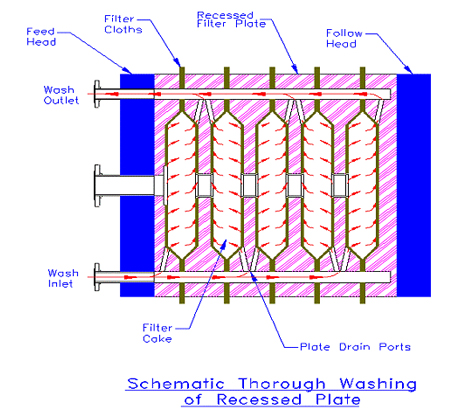 |
Figure 13 |
A filter using flush plates and frames set up for through washing has separate slurry feed and wash feed ports, and either the same or separated discharge ports for filtrate and wash liquor outlet. During thorough washing the slurry feed inlet and wash plate outlets are closed thus forcing the wash liquor entering the washing plates to flow back through the filter cloth, through the cake, through the cloth of the adjacent non-washing plate and discharge from the outlet of this plate (Refer to figure 14).
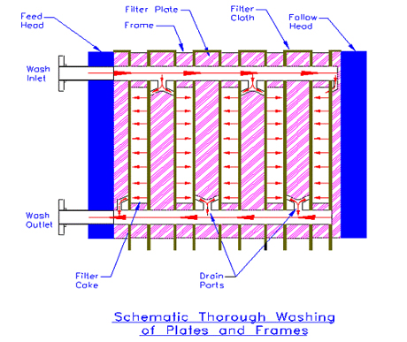 |
Figure 14 |
Blowing the filter cake with air or some other gas can be used to reduce the free moisture retained in the filter cake or in the filtrate outlet channels. As in the washing operation, air blowing can be accomplished either by simple blowing or thorough blowing.
Wash plates are normally marked by three buttons on the upper outside corner or with one button in the non-wash plates. In a plate and frame style filter, the cake frame is marked with a two-button designation.
|
|
|
|
|
| |
|
|